


Not long ago I started working on a new project at my workplace that involved developing a Shiny application. For those who don't know, Shiny is a framework for developing lightweight web applications written in R.
However, Shiny can do much more than simply show a few plots on a dashboard, and with the help of a few packages and very minimal HTML, CSS and Javascript skills, it is possible to build very eye-pleasing and functional applications.
This brief introduction was just to give you some context on where it all started, but to follow the steps in this post you don't need to be aware of Shiny at all.
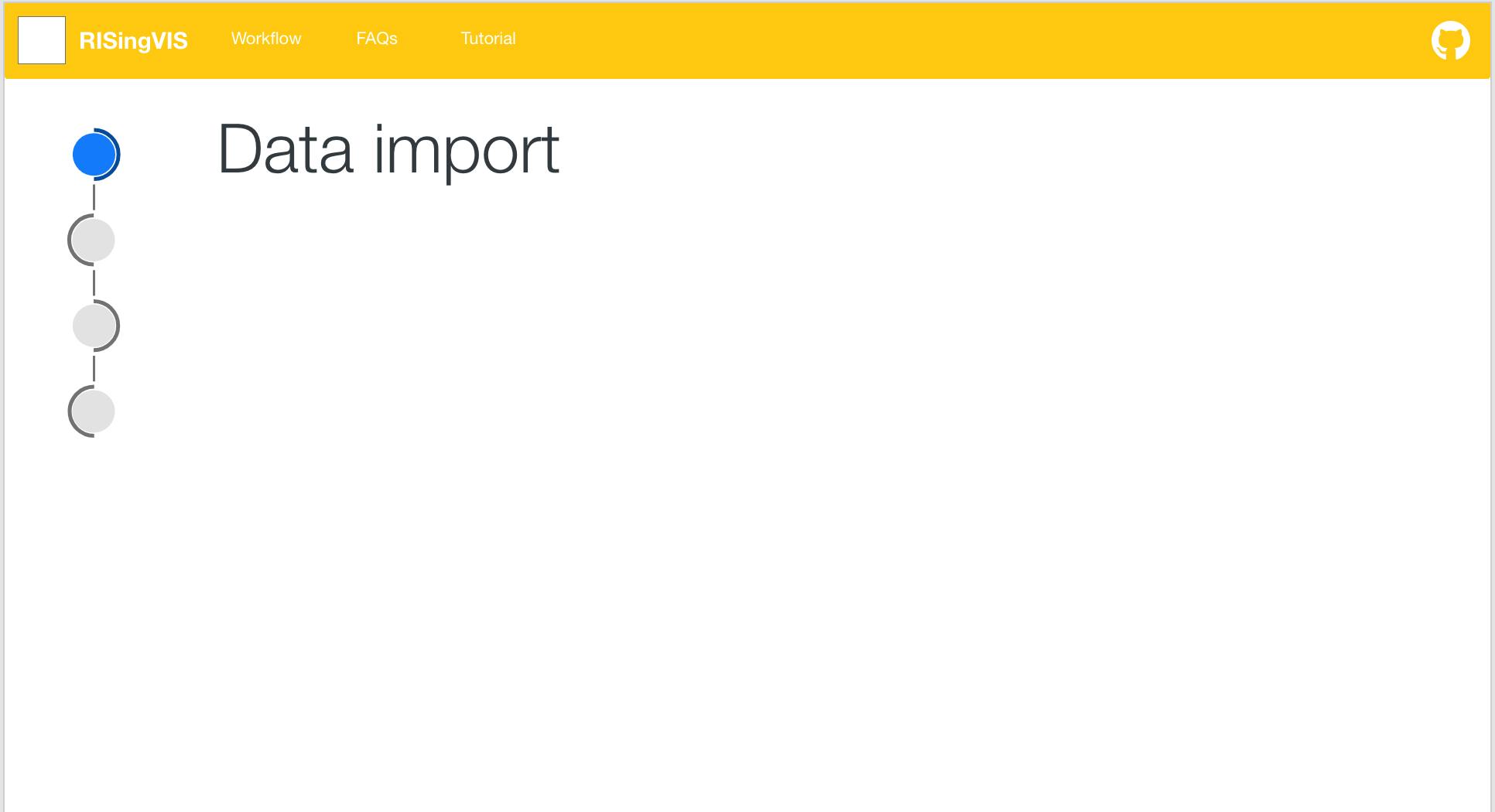
The application I'm developing has a main section in which the user can follow a standard workflow of operations, so I thought it would be nice to have a visual representation of this workflow and its steps in a form of an SVG object that would serve also as a navigation element.
Of course, it's not that difficult to achieve if you already have your complete SVG file and you just want to fiddle around with classes and ids.
However, apps are continuously evolving and subject to changes: what happens if, for example, we want to add an extra step to the workflow?
Short answer is: you have to manually fix everything - from the SVG itself to the code that supports it. Can be done? Sure. Is it convenient? Not so much.
In this post, I want to show you how I managed to build a modular SVG with a bit of Javascript so that we can adjust the number of nodes on the fly.
Where to start
As you can see from the image, the SVG is made of 2 main components:
A node
A connector
The node is further divided into a main portion (the light grey circle) and an arc.
To have a rough idea of what a single block would translate into HTML I first created the shapes in an application like Adobe XD or Inkscape.
Now, me being a bit of a noob in front-end development in general, it was time to get to know SVG a little bit better.
Things to keep in mind:
SVG has a different coordinate system from HTML or CSS - coordinates refer to the origin point of the object which is the top left corner
Each command in the path has its own syntax and meaning
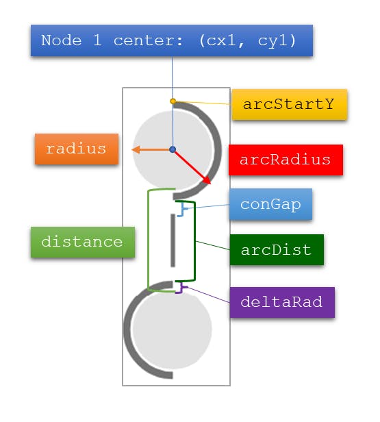
Defining the important constants
Once I had a starting point HTML-wise, I was able to extrapolate the essential elements I needed to make everything work.
const nspaceURI = 'http://www.w3.org/2000/svg';
const radius = 27.561001;
const cx1 = 34.722301;
const cy1 = 34.722301;
const distance = 2.5*radius
const arcRadius = 31.708;
const arcStartY = 3.0143021;
const deltaRad = arcRadius - radius;
const arcDist = distance - 2*deltaRad;
const conGap = 12;
Now brace yourselves because we need a little bit of math 😃.
Building the function to create a new node
First off, we need to start creating the main portion of the node (the light gray area). Depending on the numeric index of the node (starting from 1) the function will calculate where to place the shape.
In SVG, for circles, you can specify the position of the center with respect to the origin via the attributes cx and cy: since all the nodes are vertically aligned, the attribute cx will be the same for all nodes, while for cy we need to do some math.
For the first node, cy will be simply cy1 as defined in the constants above. For the other nodes instead, we need the following formula:
$$cy_{i} = cy1 + 2radius + (i - 1)distance + (i - 2)2radius$$
I know it seems complicated at first sight but it is not, let’s parse it for a second:
cy1is simply the starting y coordinate2*radiusaccounts for the fact that, since you are considering centers, between two nodes you have to count the radius of the preceding node and the radius of the current node(i - 1)*distanceadds also the fixed distance between 2 nodes(i - 2)*2*radiuscounts the whole nodes in between this node and the first one (notice that for the node with index 2, this component is equal to 0)
We can put all of this into a small function:
function calcCY(nodeIndex) {
  if (nodeIndex == 1) {
    return cy1;
  }
  if (nodeIndex > 1) {
    var cy = cy1 + 2*radius + distance*(nodeIndex - 1) + (nodeIndex - 2)*2*radius;
    return cy;
  }
}
Now we need to draw the arcs. Here the problem is a little more tricky because we don’t have circles anymore but a path element. By inspecting a little the code generated from the SVG I made with Inkscape I was able to extrapolate the essential information I needed.
Firstly, all arcs start with the declaration m (some number), (some other number): this command means “move to” and the two numbers are coordinates. More precisely, the x coordinate is the same for all arcs, while, as expected, the y coordinate changes. So again we need some formula to calculate the starting y coordinate for the arc. You can easily verify for yourself that the following one is valid:
$$arcY_i=arcStartY+(i-1)(2arcRadius+arcDist)$$
And this is the function:
function calcArcY(nodeIndex) {
  var arcY = arcStartY + (nodeIndex - 1)*(2*arcRadius + arcDist);
  return arcY;
}
The following declaration in the path starts with “a”: this stands for elliptical arc curve and looks more or less like this a (radius x), (radius y) 0 1 1 (dx), (dy). Without worrying too much about it, we notice we already have the arc radius in our constants and dx and dy are fixed for all arcs. One thing that changes, however, is the orientation of the arc between nodes with odd index and even index: to quickly change it, it is sufficient to set the flag preceding dx in the declaration - this controls whether the arc is drawn clockwise (flag set to 1) or counter-clockwise (flag set to 0).
Yay! 🥳 We already did most of the job, now let’s code a function that creates the node:
function createNode(nodeIndex, uniqueId) {
  // Node group
  var group = document.createElementNS(nspaceURI, "g");
  group.setAttribute("id", uniqueId);
  // Main node
  var mainNode = document.createElementNS(nspaceURI, "circle");
  mainNode.setAttribute("cx", cx1);
  mainNode.setAttribute("cy", calcCY(nodeIndex));
  mainNode.setAttribute("r", radius);
  mainNode.setAttribute("id", `${uniqueId}-main-node`);
  mainNode.classList.add("mini-node-main");
  // Node arc
  var arc = document.createElementNS(nspaceURI, "path");
  var clockwise = nodeIndex % 2 == 0 ? 0 : 1;
  var arcPath = `m ${cx1}, ${calcArcY(nodeIndex)} a ${arcRadius}, ${arcRadius} 0 1 ${clockwise} 0,63.4159999`;
  arc.setAttribute("d", arcPath);
  arc.setAttribute("id", `${uniqueId}-node-arc`);
  arc.classList.add("mini-node-arc");
  // compose
  group.appendChild(mainNode);
  group.appendChild(arc);
  return group
}
I attached also unique ids and classes to allow styling and put both main node and arc in a group element.
Drawing the connector
To draw the connector between two nodes the reasoning is the same but with lines becomes even easier: in this case, it is sufficient to specify the x and y coordinates of the 2 points. As usual, calculations are reserved for the y coordinates.
function addNewConnector(nodeIndex, uniqueId, svgId) {
  var line = document.createElementNS(nspaceURI, "line");
  line.setAttribute("id", uniqueId);
  line.setAttribute("x1", cx1);
  line.setAttribute("x2", cx1);
  var y1 = arcStartY + nodeIndex*2*arcRadius + (nodeIndex - 1)*arcDist + conGap;
  var y2 = y1 + (arcDist - 2*conGap);
  line.setAttribute("y1", y1);
  line.setAttribute("y2", y2);
  line.classList.add("mini-node-connector");
  var svgObj = document.getElementById(svgId);
  return svgObj.appendChild(line)
}
Fixing the viewBox
When adding new nodes like this to an existing SVG element it is important to also fix the viewBox and height of the object otherwise your additional elements won’t show.
To do that it is sufficient, with all the given constants, to calculate the total height at the given index:
function adjustViewBox(svgId, nodeIndex) {
  var totHeight = 2*arcStartY + nodeIndex*2*arcRadius + (nodeIndex-1)*arcDist;
  var svgObj = document.getElementById(svgId);
  const newVB = `0 0 72.021 ${totHeight}`;
  svgObj.setAttribute("viewBox", newVB);
  svgObj.setAttribute("height", totHeight);
}
Putting everything together
In this CodePen I just demonstrated all of what I wrote above by attaching a function to the click event of a button. What the function does in order is:
If it’s not the first node it creates the connector to the previous node
Create and add the node
Adjust the viewBox and height
And that's it :D we just have our modular SVG builder with a bit of math and a few lines of code.
I hope you enjoyed this tutorial, thanks for reading, see you soon!